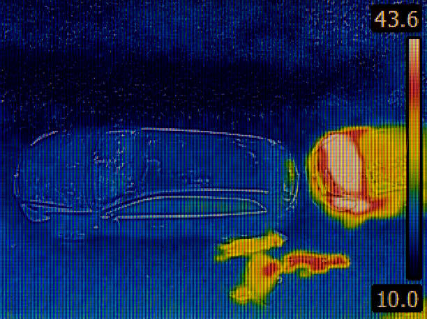
Thermal imaging calibration for reliable buried pipe anomaly mapping
Reliable mapping of buried pipe anomalies depends on calibrated thermal systems and integrated diagnostics. This article explains how thermal imaging works with acoustics, fiberoptics, pressure sensors, and telemetry to improve subsurface pipeline and waterworks monitoring.

Effective mapping of buried pipes requires more than a single sensor: it depends on a calibrated thermal imaging workflow combined with complementary diagnostics. A properly calibrated thermal camera can translate subtle temperature differences into consistent anomaly maps, while integrated systems—acoustics, fiberoptics, pressure sensors, and telemetry—help distinguish true leaks from benign subsurface variations. This article outlines calibration practices and explains how multisensor data and analytics support reliable pipeline and waterworks tracing and monitoring.
Can acoustics complement thermal imaging?
Acoustic methods detect sound signatures from flowing water or gas in a disturbed pipe environment. When paired with thermal imaging, acoustics helps confirm whether a thermal anomaly corresponds to an active leak or merely a shallow soil temperature variation. Acoustic sensors are especially useful in metal and plastic pipelines where thermal contrast is low, providing an independent modality for diagnostics and strengthening confidence in anomaly mapping.
Acoustic data can be fed into the same analytics pipeline as thermal imagery, allowing correlated event detection. This multimodal approach reduces false positives and improves the spatial accuracy of subsurface tracing when used alongside calibrated thermal maps.
What role do sensors and pressure telemetry play?
Pressure sensors and telemetry provide continuous operational context that static thermal snapshots cannot. Sudden drops or oscillations in pressure telemetry often precede or coincide with thermal anomalies; combining these streams helps distinguish transient system events from persistent leaks. Accurate timestamps and synchronized telemetry are essential for aligning pressure events with thermal frames during post-processing.
In practice, pressure sensors mounted on pipeline segments provide baseline behavior, while remote telemetry transmits data to central monitoring. This continuous data supports both real-time diagnostics and historical analytics to validate thermal-based mapping results.
How does fiberoptics enhance subsurface tracing?
Fiberoptic sensing, such as distributed temperature sensing (DTS) and distributed acoustic sensing (DAS), offers continuous, high-resolution profiles along a pipeline corridor. When fiberoptics are deployed alongside or near buried pipelines, they capture temperature and vibration patterns that can be correlated to thermal imaging anomalies, enabling precise subsurface tracing and localization.
Fiberoptic DTS can highlight where soil or fluid temperatures diverge along a pipeline, while DAS captures acoustic signatures complementary to discrete acoustic sensors. Combined datasets improve mapping granularity and support advanced diagnostics for complex infrastructure networks.
How are mapping and monitoring integrated?
Mapping uses periodic surveys—thermal flights, ground-based imaging, or DTS sweeps—to build spatial representations of anomalies. Monitoring relies on continuous telemetry and sensor feeds to detect changes over time. Integration occurs when calibrated thermal maps are augmented with live sensor streams, enabling automated alerts and prioritized inspection tasks.
A structured monitoring program defines thresholds informed by calibration data so that anomalies detected by thermal imaging trigger verification steps using pressure readings, acoustics, or fiberoptic traces. This reduces unnecessary excavations and improves maintenance planning.
Which analytics and diagnostics aid detection?
Analytics convert raw thermal, acoustic, pressure, and fiberoptic data into actionable insights. Techniques include noise filtering, temporal smoothing, spatial clustering, and probabilistic diagnostics to rank anomalies by likelihood. Machine-assisted analytics can learn site-specific baselines after calibration, improving sensitivity while controlling false alarm rates.
Diagnostics combine cross-sensor correlation and historical patterns to suggest root causes—corrosion, joint failure, third-party damage, or groundwater influence. Clear diagnostic outputs help field teams select the right tracing method and measurement tools for verification.
How is calibration applied in waterworks pipeline projects?
Calibration begins with reference measurements: known thermal targets, controlled flow scenarios, and baseline soil temperature profiles. For waterworks pipelines, seasonal variations in soil moisture and ambient temperature must be included in calibration models to ensure consistent anomaly thresholds. Calibration also addresses camera properties—emissivity settings, lens characteristics, and environmental reflections—so thermal images translate accurately to temperature differences.
Field calibration often includes coordinated checks with pressure sensors and tracer tests to validate that mapped anomalies correspond to true leaks or other faults. Documentation of calibration parameters and periodic recalibration schedules ensures sustained mapping reliability across inspection campaigns.
Conclusion
Reliable buried pipe anomaly mapping relies on calibrated thermal imaging supported by a suite of complementary technologies. Acoustics, fiberoptics, pressure sensors, and telemetry each contribute unique signals; when fused through robust analytics and diagnostics, they improve the precision of subsurface tracing and monitoring. Systematic calibration and synchronized datasets reduce false positives and enable more targeted, evidence-based maintenance decisions.


