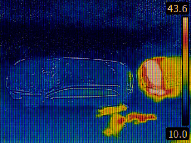
Thermal Imaging Protocols for Detecting Concealed Pipe Anomalies
This article outlines practical thermal imaging protocols for locating concealed pipe anomalies. It explains how thermal and complementary methods are applied, how sensors and calibration affect results, and how survey workflows support diagnostics and monitoring in subsurface pipeline systems.

Thermal imaging offers a non-invasive way to locate concealed pipe anomalies by detecting temperature contrasts at the surface that correspond to subsurface flow or leaks. Effective protocols balance equipment settings, environmental considerations, and integration with other sensing modalities. Consistent procedures help teams distinguish true anomalies from background thermal noise, account for pressure and flow effects, and produce mapping outputs suitable for diagnostics. This article presents structured steps for planning, calibrating, surveying, and interpreting thermal data for pipeline applications while highlighting how acoustic and sensor data can strengthen confidence in findings.
How does thermal imaging detect subsurface anomalies?
Thermal imaging captures infrared radiation differences on surfaces that result from heat transfer caused by subsurface conditions. A leak or flow anomaly in a buried pipeline can create localized cooling or warming of soil or pavement depending on fluid temperature relative to the environment. Protocols require selecting the right spectral range and resolution, timing surveys to exploit diurnal temperature gradients, and documenting ambient conditions that influence surface expression. Thermal contrasts are often subtle; controlled temperature differentials, such as surveying during early morning or late afternoon, can improve visibility of subsurface anomalies.
How do acoustic and sensors integrate with imaging?
Acoustic techniques complement thermal surveys by detecting pressure waves or flow noise associated with leaks. Sensors placed along a pipeline—such as hydrophones, accelerometers, or fiber-optic distributed acoustic sensing—can localize events that thermal imagery then targets for surface verification. Effective protocols coordinate temporal alignment between acoustic detections and thermal imaging, correlating acoustic timestamps with thermal frames. This multimodal approach reduces false positives: where thermal signatures are ambiguous, acoustic or in-line sensor evidence can confirm whether a detected thermal anomaly corresponds to an active leak or transient operational effect.
What are calibration, pressure, and flow considerations?
Calibration of thermal equipment and understanding pipeline operating conditions are central to reliable diagnostics. Regular radiometric calibration ensures temperature accuracy; emissivity settings must be adjusted for surface materials like asphalt, concrete, or vegetation. Knowledge of internal pipeline pressure and flow regime informs expected thermal behavior: pressurized leaks can produce stronger thermal signals than slow seepage, while temperature of transported fluid relative to ground temperature determines contrast polarity. Protocols should record system pressure, flow rate, and fluid temperature at the time of surveying to contextualize imaging findings.
How should pipeline mapping and surveying be organized?
Survey planning begins with pipeline maps, access points, and environmental reconnaissance. A systematic mapping workflow sets corridor widths, imaging altitudes for drone-based surveys, or transect spacing for handheld systems. GPS-tagged thermal imagery is essential for creating georeferenced mapping layers that document anomaly locations. Surveys should include overlapping passes and ground-truth checks, such as spot thermometers or targeted excavation where feasible. Metadata capture—time of day, weather, instrument settings—enables reproducibility and supports later comparison for monitoring trends.
What best practices apply to diagnostics and data interpretation?
Interpreting thermal data requires layered analysis: raw imagery, corrected radiometric maps, and time-series comparisons. Image processing steps include atmospheric correction, emissivity compensation, and noise filtering. Look for spatially coherent patterns consistent with expected subsurface geometry rather than isolated pixels. Combine thermal evidence with acoustic hits, pressure fluctuations, or in-line inspection reports to build a diagnostic case. Document uncertainty ranges and, where appropriate, recommend follow-up investigations like leak pinpointing with tracer gases or targeted excavation for confirmation.
How do surveying protocols support monitoring and local services coordination?
Routine monitoring protocols schedule periodic thermal surveys to detect emerging anomalies and verify repairs. Standard operating procedures should specify equipment calibration intervals, personnel qualifications, and data management practices. When engaging local services, share georeferenced anomaly reports and context—pressure, flow, and recent maintenance—to allow coordinated response. Clear handoffs between imaging teams and field crews reduce diagnostic delays. Local conditions, permitting, and access agreements should be addressed in advance to ensure surveys proceed efficiently.
Conclusion
Thermal imaging protocols for concealed pipe anomaly detection rely on careful planning, reliable calibration, and integration with acoustic and sensor data to improve diagnostic confidence. Consistent metadata collection and georeferenced mapping create actionable outputs for monitoring and repair prioritization. Following standardized workflows helps distinguish genuine subsurface issues from environmental noise and supports safer, more efficient pipeline management.


